Difficulty
Easy
Steps
23
Time Required
00:20:00
- Getting Started With Duet Software 12 steps
- How to unbox your unit 11 steps

In Progress
This guide is currently being written. Reload periodically to see the latest changes.
Tools
No tools specified.
Parts
-
-
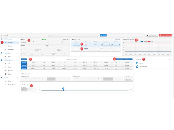
If you are new to the Duet ecosystem we will start by highlighting what functions are available in each category. We will dive deeper into each category in upcoming steps
-
1. This button opens and closes the drawer to the categories.
-
2. This is the name your network will see.
-
3. You can quickly input gcode and send it from this terminal.
-
4. With this button you can quickly upload a file and it will immediately start printing the uploaded file.
-
5. This button will shut down and restart the firmware on your unit.
-
6. The dashboard gives you access to basic functions: Movement, Extrusion, Fan Control and Macros.
-
7. Console is where you send large amounts of gcode directly, and where information will be reported.
-
-
-
8. Height Map, this will show the read out of a grid probe. This is unneeded for everyday use.
-
9. Status shows information for the current print. Once a print begins you will automatically be switched to this category.
-
10. Full list of uploaded files that can currently be printed.
-
11. Macros are where you can view, edit and add new macros.
-
12. Filaments, this is currently not being used but will be in the future. At that time we will dive deeper into it.
-
13. System is where you can access the firmware settings such as the Config.g file.
-
14. General, this will show you the current Duet Web Control Software.
-
15. Machine - Specific will tell you the current electronics and you can adjust drop down temperature options to fit your current needs.
-
-
-
1. Using the navigation drawer is the fastest way to get to the General category.
-
2. Status: this will tell you the current X, Y and Z coordinates, Voltage and Speeds.
-
3. Tools: This is where you can set your hotend (Tool) temperature. You can either use a drop down or enter it manually.
-
4. Bed: You can set you bed temperature here either by drop down or entered manually.
-
5. Temperature Chart: This will give you a live chart of temperatures.
-
6. Machine Movement: Here you can move the machine, either by preset values or you can right click and change the values temporarily.
-
7. Fan Control: Here you can adjust your fan speed on the fly if needed but it is automatically set by your sliced file during a print.
-
8. Macros: These are quick lines of code you can run to automate tasks such as a leveling routine or loading and unloading material. You can make your own macros and add them to this list. This will be addressed in the Macro category.
-
-
-
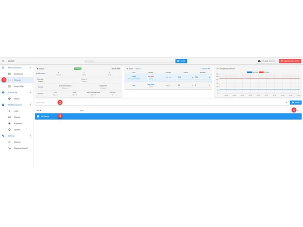
1. Using the navigation drawer is the fastest way to get to the Console category.
-
2. Here you can enter gcode manually to run immediately.
-
3. The area will give you activity feedback. This will also be the place you will get the readout after running diagnostics.
-
4. Here you can clear the read out or save all the info that has been posted for trouble shooting.
-
-
-
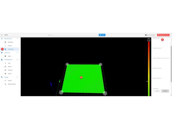
1. Using the navigation drawer is the fastest way to get to the Height Map category.
-
2. This area will give you read out information from a grid probe.
-
3. This is a visual representation of your grid probe.
-
Since we use "true leveling" and Mesh Compensation, as long as the map is green you are in good standing.
-
-
-
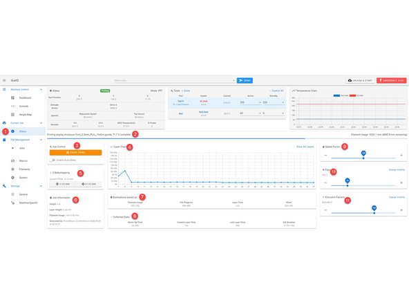
1. Using the navigation drawer is the fastest way to get to the Status category.
-
2. This is your progress bar for your current job (print)
-
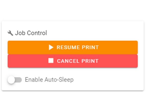
3. Job Control: This lets you pause, resume or cancel a current job. Once a job is finished you can restart the previous job.
-
4. Layer Chart: This give you a layer by layer time chart.
-
5. Z Baby Stepping: When you begin a print, if your nozzle is too close to or too far from the bed you can adjust it on the fly. Arrows pointing towards each other mean the nozzle will get closer to the bed, arrows pointing away the nozzle will move farther from the bed.
-
6. Job Information: This will give you the general information for the job currently underway.
-
7. Estimations based on: These are only estimations, the longer the print goes the more accurate these will be. The most accurate estimations come from simulation under the jobs category.
-
8. Collected Data: This is info collected from the current job.
-
-
-
9. Speed Factor: Here you can actively adjust the speed of your print.
-
10. Fans: Here you can actively adjust fan speeds.
-
11. Extrusion Factors: Here you can actively adjust extrusion percentage.
-
-
-
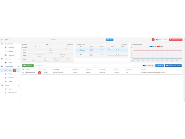
1. Using the navigation drawer is the fastest way to get to the Jobs category.
-
2. Upload & Start: Using this button to upload a file will cause the print to start immediately, do not do this if you already have a file started or you are wanting to start another file. If you need to upload several files, do it in the Jobs category.
-
3. This is where all of your uploaded files will be listed and will be available for reprinting without having to reupload.
-
Simulation: If you need an accurate print time right click on the job and select "Simulate File". It will take a few minutes but will give you the actual print time. This is highly recommended if you are quoting out a print job.
-
-
-
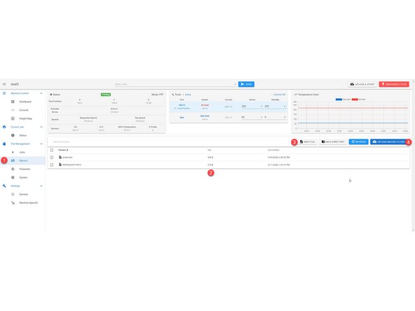
1. Using the navigation drawer is the fastest way to get to the Macros category.
-
2. Here all of the macros are listed. You can edit any of the macros by right clicking on the name and selecting "Edit". Please only do this if you know what you are doing.
-
3. New File: With this button you can create a new macro that fits your current needs.
-
4. Upload Macro Files: Here you can upload macro files we provide you. If you do not feel comfortable making your own macros let us know and we can make it for you.
-
-
-
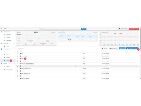
1. Using the navigation drawer is the fastest way to get to the System category.
-
2. Config.g: If you are receiving support this will most likely be the only file we ask you to access. Any time you are asked to make a change to this file please right click and download this file to have a backup.
-
3. Upload System Files: When doing a firmware update we will have you select this button and upload a zip file. Please only do this with updates directly from us.
-
-
-
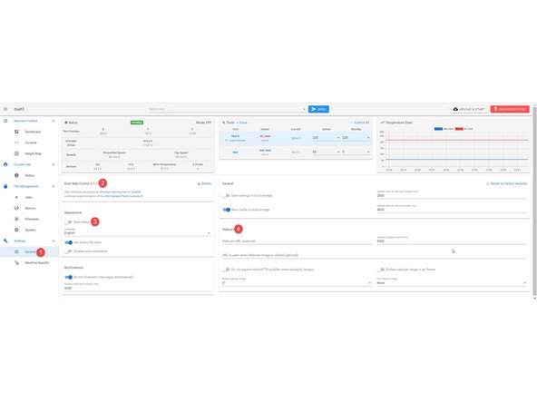
1. Using the navigation drawer is the fastest way to get to the General category.
-
2. During support you may be asked what Duet Web Control version you are running. It can be found here.
-
3. Here you can toggle between the displayed light theme or a dark theme.
-
4. In the near future we will be posting a step by step guide to add your own webcam along with a kit provided by us.
-
-
-
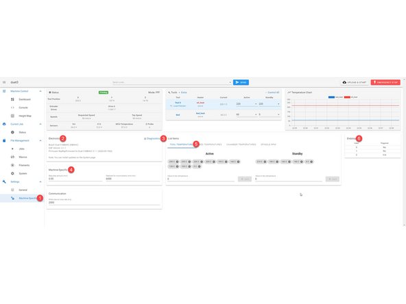
1. Using the navigation drawer is the fastest way to get to the Machine Specific category.
-
2. This tells you the type of electronics installed in your unit.
-
3. Diagnostics: During support you will be asked to send us the diagnostics report, click this button and it will give you a read out in console.
-
4. Machine Specific: We do not recommend changing these settings unless instructed or you know what you are doing.
-
5. Tool and Bed Temperatures; Here you can add or remove temperatures from the drop downs in the "Tools" section at the top of the web interface. If you use specific materials that need different temps feel free to add them.
-
6. Endstops: During support you may be asked if your endstops are being triggered; you will be be able to see that here.
-
-
-
Move your box to a floor ensuring the box is upright.
-
Cut the tap at the top of the box
-
-
-
Open the box and remove the top foam
-
-
-
(We recommend having two people for this next step)
-
With one person on opposite sides of the box. Each person should grab the top aluminum with one hand and the top of the box with the other.
-
Pull up evenly on both sides of the unit while pushing down the box.
-
Once the unit is free from the box, center foam, and base foam please the unit on a table.
-
-
-
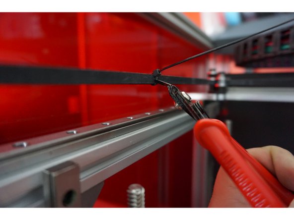
Now you should remove the zip ties from the XY belt system.
-
Gently push your gantry towards the Y max (Rear of the unit)
-
-
-
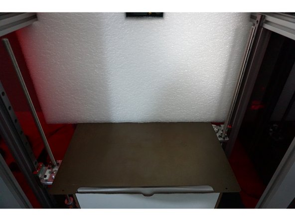
Slide the bottom white box from under the bed and set it to the side.
-
-
-
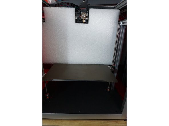
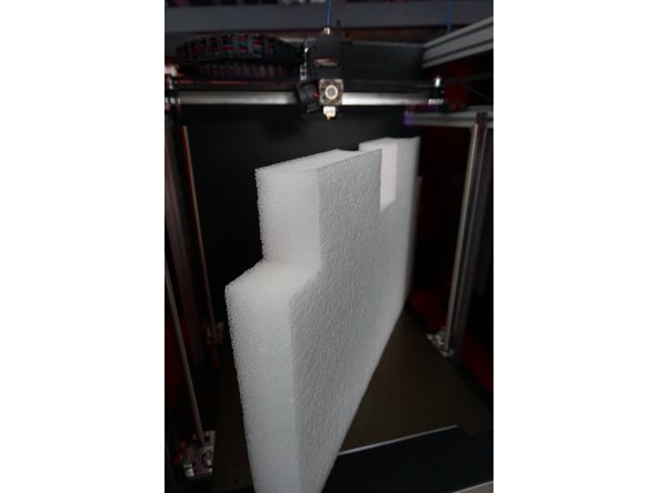
Pull the interior foam out of the unit, it is okay if the front of the bed drops slightly but do not move it all the way down.
-
-
-
Move to the White Box that was removed from below the bed.
-
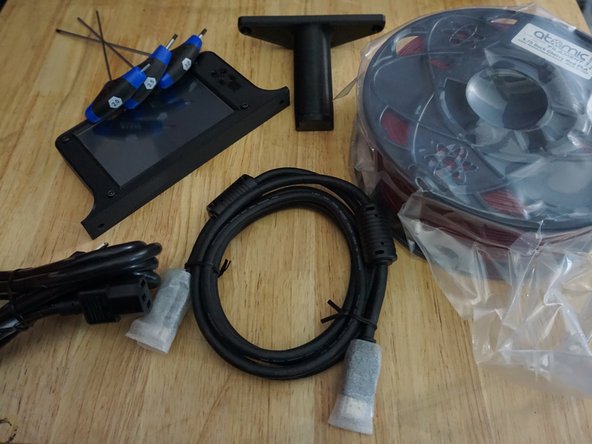
Inside the White Box, you will find the following:
-
1kg spool of filament for first prints.
-
Power Cable and HDMI Cable (for diagnostics)
-
USB stick
-
5in Touch Screen and Spool Holder (Two M5x10 bolts to mount the spool holder and two M5x10 bolts to mount the display)
-
Tools: T-Handle Hex 2mm, 2.5mm, 3mm
-
Filament sensor with bowden tube (one M5x10mm bolt for mounting filament sensor)
-
-
-
If you intend to use a wall-mounted spool holder or RepBox, you do not need the spool holder
-
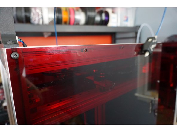
On the right side of the printer, locate the second and third bolts across the top edge from the front that holds the acrylic to the aluminum.
-
Remove the second and third bolt, these bolts will no longer be used.
-
Mount your spool holder using the two M5x10 bolts included.
-
-
-
On the right side of the printer, locate the fourth bolt across the top edge from the front that holds the acrylic to the aluminum.
-
Remove the fourth bolt, this bolt will no longer be used.
-
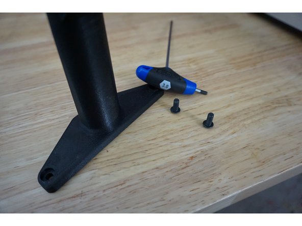
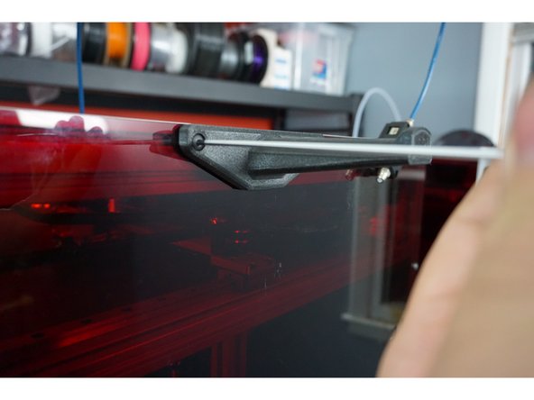
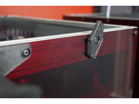
Mount the Filament Sensor mounting plate with the included M5x10mm bolt
-
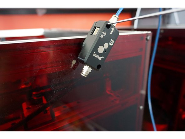
Mount the Filament Sensor to the mounting plate with the included M3 Bolts ensuring the bowden tube is coming out of the top of the sensor.
-
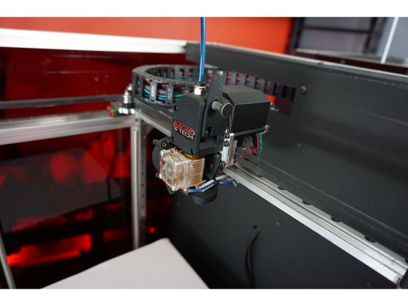
Insert the other side of the bowden tube into the BondTech Extruder.
-
-
-
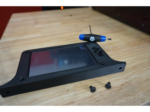
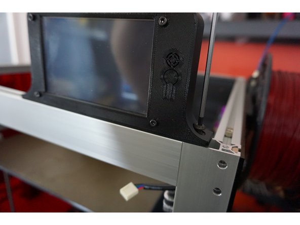
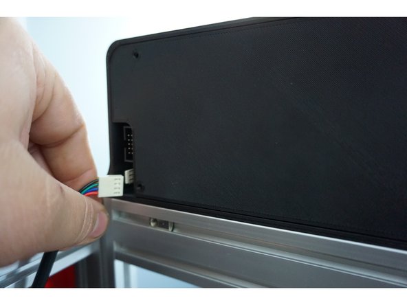
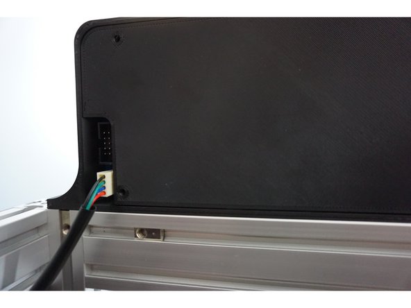
On the top of the unit, your display will mount across the front extrusion.
-
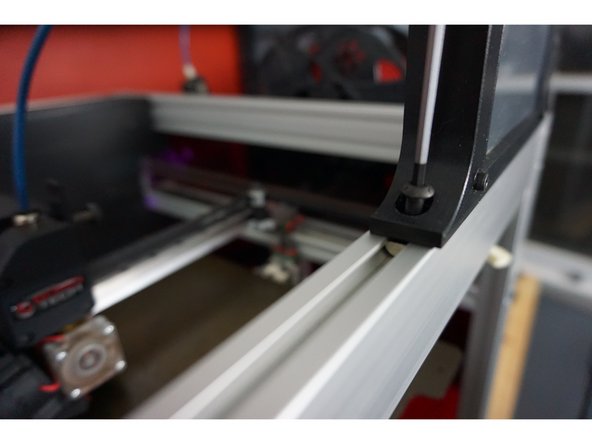
The right M5x10 bolt will go into the tapped end of the aluminum
-
The left M5x10 bolt will go into the slidable nut.
-
-
-
Once the screen is mounted, plug in the screen. The plug is keyed so you can only plug it in one way.
-