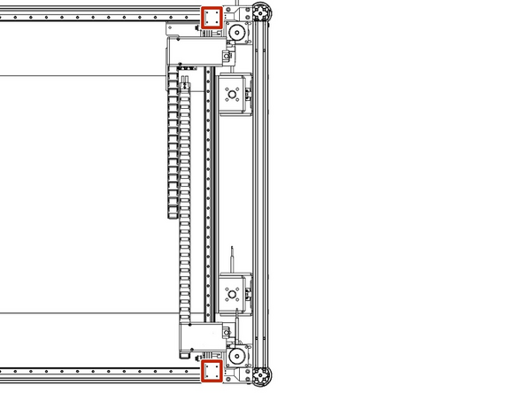
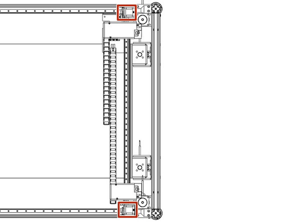
Parts
No parts specified.
-
-
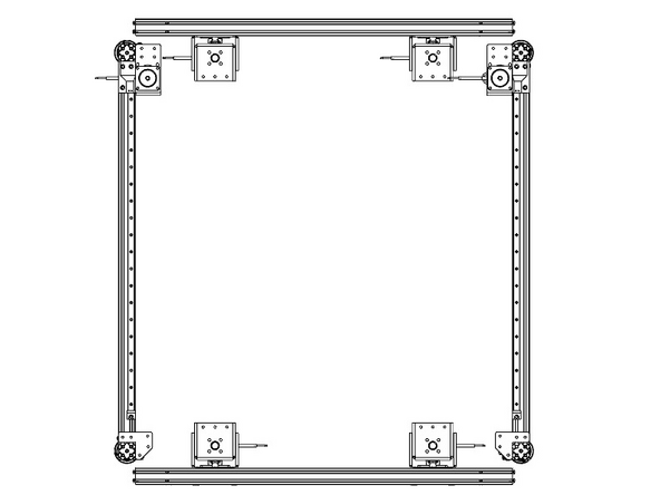
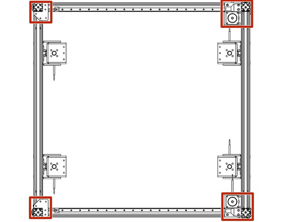
After unpacking your unit the first step is to lay out the front and back frame panels. These are your Y axis and you can tell they are the front and back by them having the stepper, idler mounts and Y belts on both.
-
While they are laid flat the motors and idler mounts will be facing up.
-
Next, you need to ensure that the brakes on the casters are lowered to ensure the frames won't roll when standing them up. If they need to be adjusted there is a red knob inside the caster to raise and lower the brake.
-
-
-
Parts needed
-
Front and Rear frames (they should already be laid out from the previous step)
-
Left and right frames, these both have the z axis assemblies installed on them. These are also called the X Frames
-
On both X Frames you will need to check the M5 bolts are backed out about 5mm from the end of the 4040 extrusions.
-
There are 4 M5x12mm bolts in each end of the 4040 extrusion. In this step, you will be checking a total of 32 bolts, 16 on each side panel.
-
-
-
Have Person 1 stand between the two Y frames while Person 2 stands each of the Y Frames up one at a time. Person 1 will hold both of the Y Frames upright roughly 900mm apart.
-
While Person 1 is holding the Y frames double-check that both stepper motors are both on the inside of the frame.
-
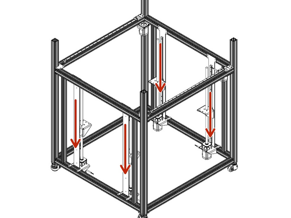
Next, Person 2 will slide each of the X Frames into place on each side, one at a time.
-
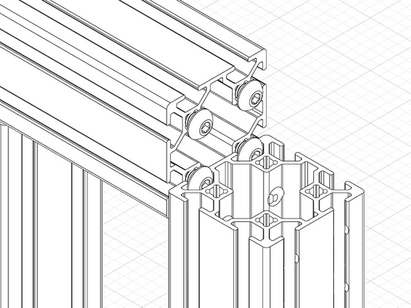
When starting you must be sure that the heads of the bolts (the ones checked in the previous step) are sliding into the upright channels in the Front and Rear Y Frames.
-
The X Frames will slide all the way down until they rest on the Caster mounts.
-
If you are having trouble, first check that the bolts are backed out roughly 5mm. Next have Person 1 adjust the Front and Rear Y Frames so they are parallel to each other and as close to 90 Degrees to the X Frame. If they are angled or not parallel you may get binding.
-
-
-
Needed Parts
-
3mm hex wrench or T Handle
-
12- M5x8mm bolts
-
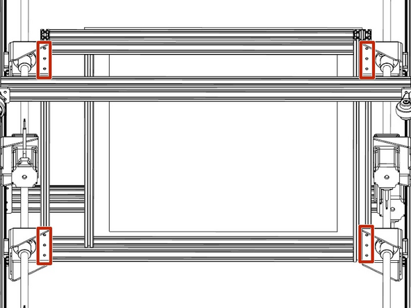
In this step you will slide the Stepper Motor Mounts and Idler Mounts into place and secure them.
-
First, you will need to loosen the M5 bolts that hold the Stepper Motor and Idler Mounts just enough to allow them to slide. Do not remove the bolts.
-
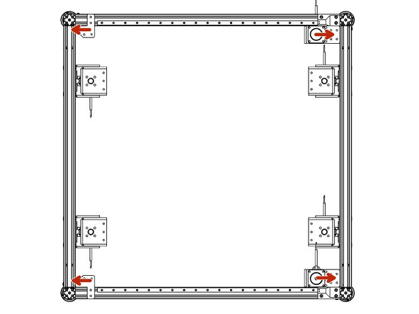
Slide the Stepper Motor and Idler Mounts into their respective corners where the X and Y frames join.
-
In the X Frame there should be t-nuts installed allowing you start 4 M5x8 bolts to mount the Motor Mounts and 2 M5x8mm bolts for the Idler Mounts. Leave them loose for now.
-
-
-
Tools Needed
-
3mm hex wrench
-
2- Assembly Jigs
-
4-M5x8 and Spare T Nuts
-
Clamp
-
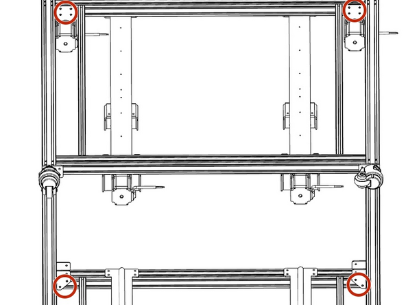
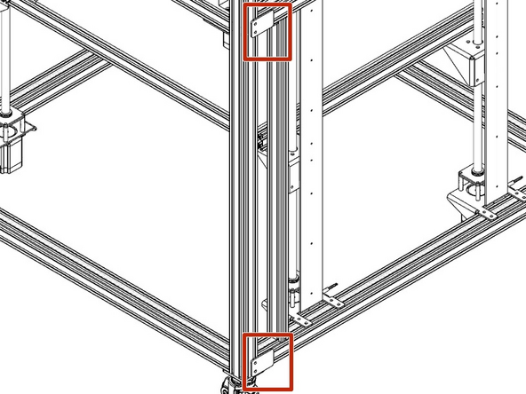
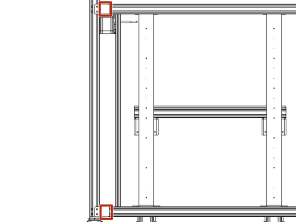
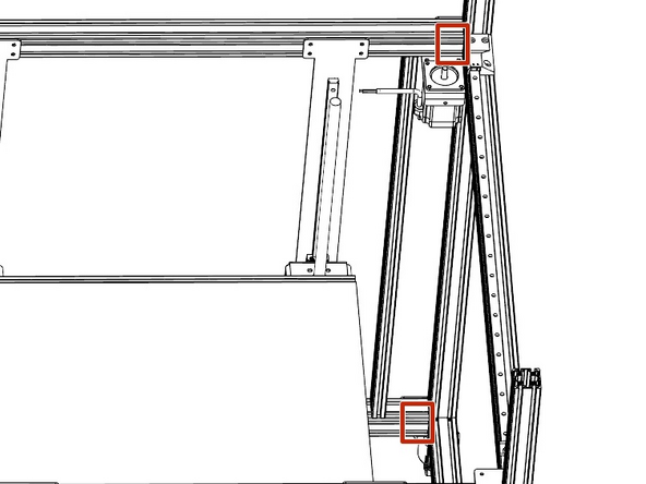
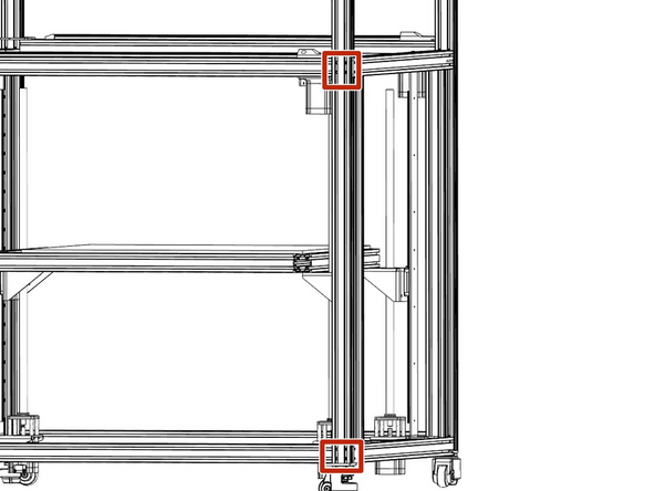
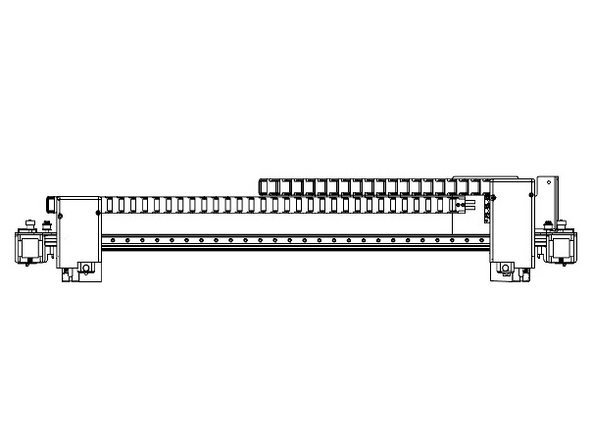
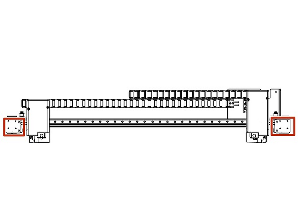
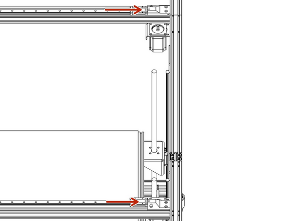
Start on one corner and place the assembly jigs on the outside of the of the Y Frame Uprights overhanging the Top and bottom X Frame extrusions.
-
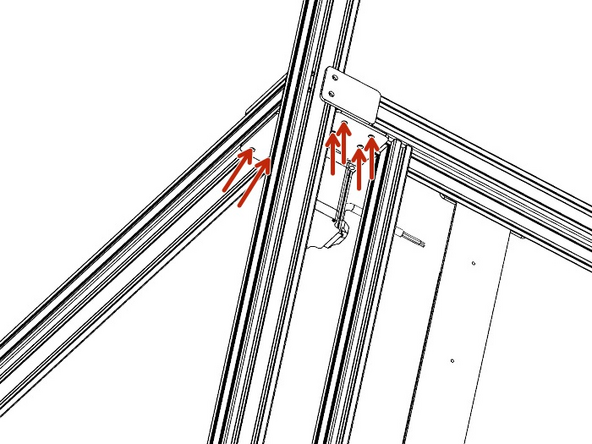
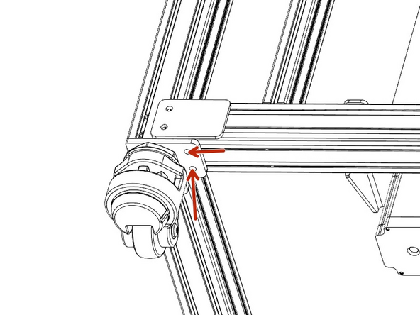
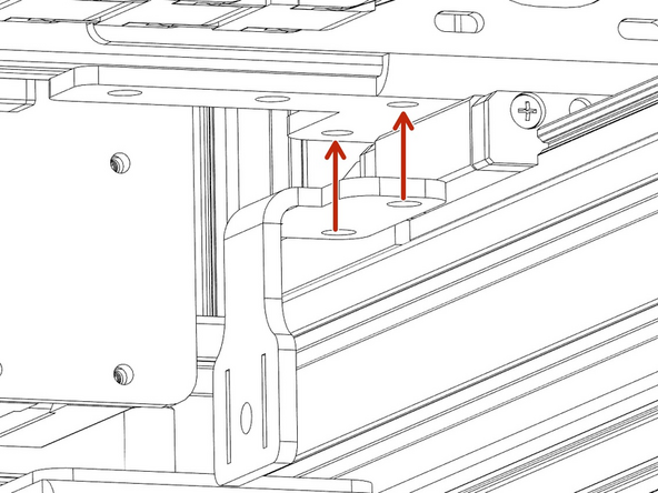
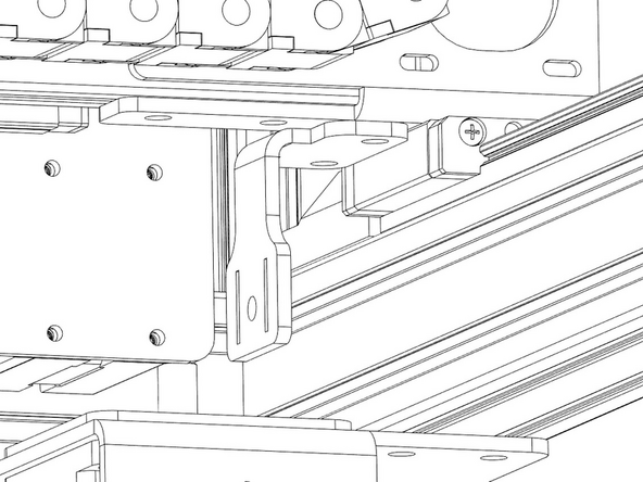
Clamp the X Frame extrusions to the Assembly Jigs. The faces where the clamps should be placed are in picture 2 and 3
-
-
-
DOUBLE CHECK: ensure that the mounts are secured on X and Y Frames and the X Frame is clamped to the Assembly Jig
-
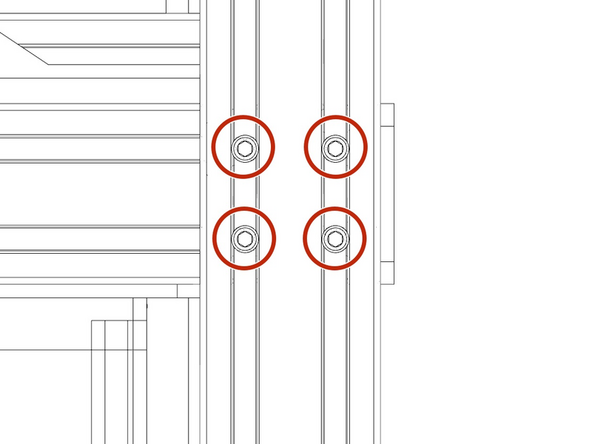
Use the clearance holes in the Y frame to tighten the 4 M5 bolts at the end of each of the X Frame Extrusions. Each corner will have 8 bolts to tighten.
-
Once they are tight and the jigs and clamps are removed. Check that the X Frame is flush with the Y upright extrusion.
-
Repeat this step on all 4 corners.
-
-
-
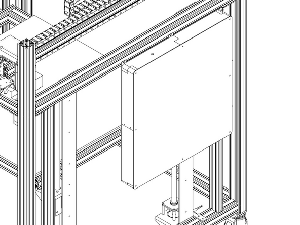
In this step, we will be ensuring the bed is laid out in the correct orientation.
-
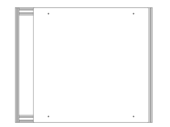
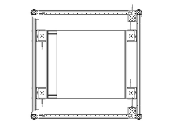
You will notice that the aluminum bed plate is offset to one side. The side of the bed that has the aluminum plate shifted towards goes towards the stepper motor side of the printer.
-
-
-
Tools Needed
-
12-M5x8mm bolts
-
3mm hex wrench or T handle.
-
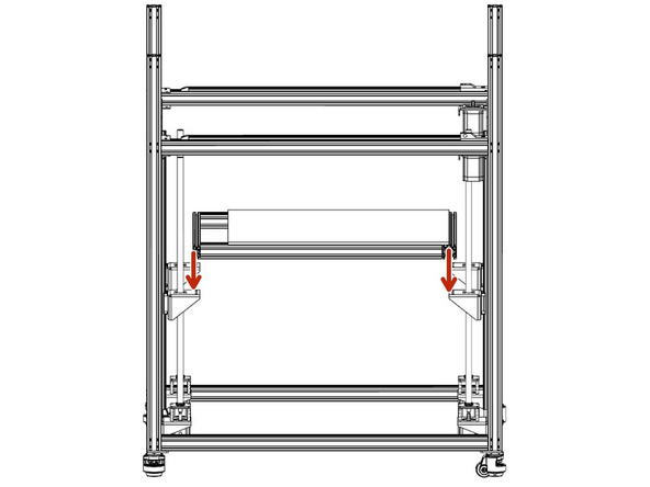
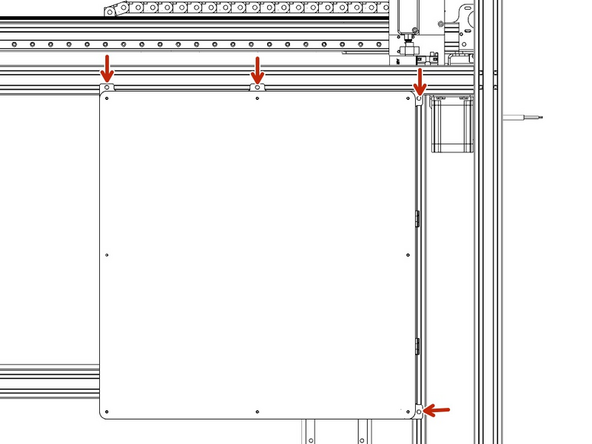
With two people lift the bed assembly and place the bed frame on top of the Z yokes.
-
Carefully center the bed on the yokes front to back.
-
There should be T Nuts installed in the bed frame, extra T Nuts have been supplied if needed.
-
Using M5x8mm bolts, secure the bed frame to the Z yokes from the bottom. There are 3 bolts from the bottom.
-
-
-
In this step we will be removing the X and U motors to allow access for mounting the XU Axis on the Y Axis. Please be mindful of the hotends to ensure they aren't damaged while prepping this component.
-
First unplug the stepper wiring harness from the top of the stepper motors on both the X and U
-
Using a 2.5mm Hex Wrench or T-Handle loosen the 4 bolts on each motor and set the motors to the side
-
-
-
Now that the XU axis is prepped, slide the Y carriages to the endstops (towards the motors)
-
With two people lift the XU axis and place it on the Y carriages
-
Have one person hold the gantry in place while the second person starts 4 M3x6 bolts into the Y carriages.
-
The XU gantry is back heavy so are not careful the gantry will roll back unless held in place until the bolts are started into the Y carriages.
-
With one person applying slight pressure in the center of the gantry to press it into the endstops, the second person tightens the M3 bolts into the Y carriages in an X pattern.
-
Reinstall the X and U motors with 4 M3x8 bolts and plug them back in.
-
Be sure the slide the belt on the motor pulley and that it is still on the idler on the opposite side. Belt tightening will be another step.
-
-
-
Next, using 4 M5x6 bolts and a 3mm Hex/T-Handle secure the Y Belt Clamp to the bottom XU axis on both sides.
-
The Y belt will be tightened in another step.
-
-
-
In this step, we will be mounting the Y-axis cable chain.
-
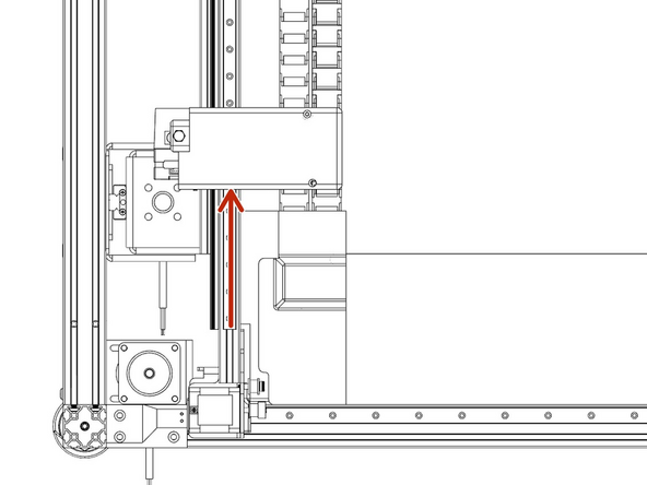
Slide the U print head towards the center of the printer.
-
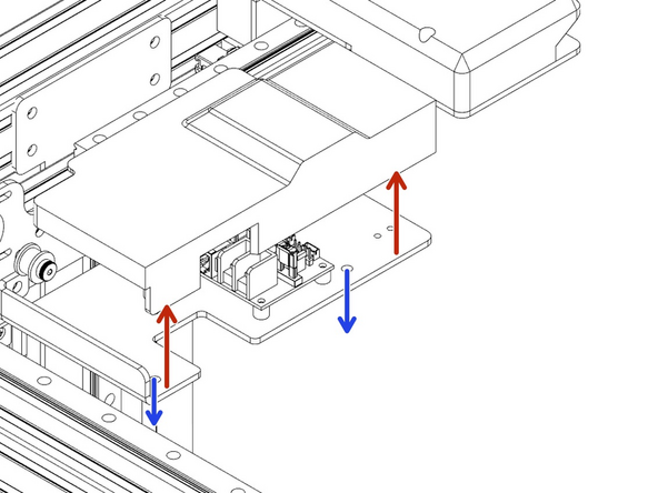
Using an 3mm hex wrench to loosen the two bolts in the bottom of the electronics cover on the XU axis. (Blue arrows)
-
Lift the cover off (Red Arrows)
-
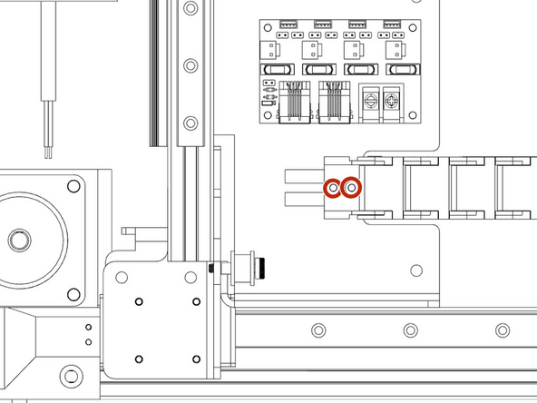
Using an 2.5mm hex wrench secure the Y axis cable chain to the electronics bracket.
-
Plug the Y plugs into each other being mindful of the labels. You will have a U Motor, X Motor, Power, and CAN plugs.
-
Replace the cover with the two M5 bolts from the bottom of the electronics bracket.
-
-
-
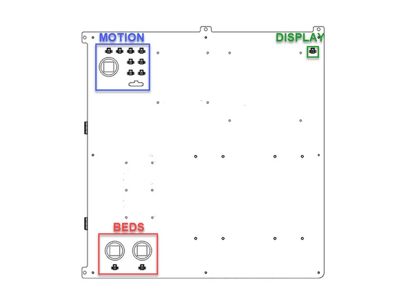
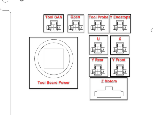
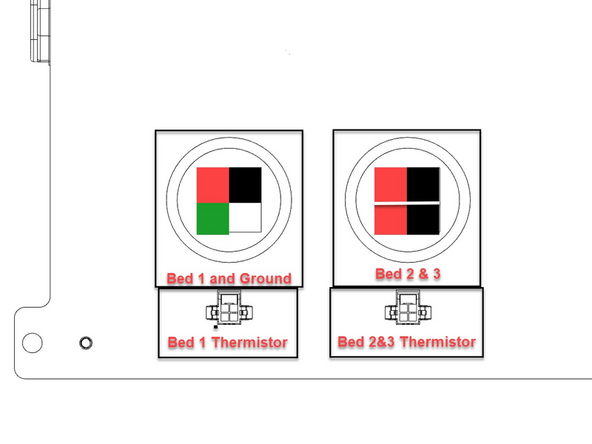
Next we will become familiar with the plugs on the electronics box. They are broken into 3 areas
-
The Motion area has all of your motors, end stops, and tool head plugs. Once mounted you will use this layout and the wire labels to plug this in correctly.
-
The Bed area has the plugs for the bed/s and thermistors. Bed 1 and the grounding wire are on all machines, the 1200 and 1800s will have the additional plugs for Bed 2/3 depending on the machine size.
-
The Display area has one plug that will be routed up to the 7in Touch Screen.
-
-
-
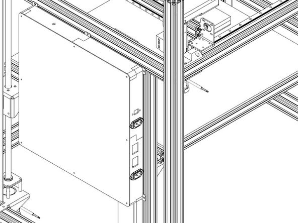
The Electronics box will be installed on the right side of the machine (Y Motor side)
-
T Nuts should be installed in place but if they have moved or need to be replaced, extras will be supplied.
-
Having one person holding the electronic box up, have a second person verify that the t nuts are in place or replace them if needed.
-
Have the second person mount the electronics box with 4 M5x8 bolts and a 3mm Hex wrench while the first person holds the electronic box in place.
-


