Difficulty
Very easy
Steps
19
Time Required
00:05:00
- How to unbox your unit 11 steps
- Getting Connected 8 steps

In Progress
This guide is currently being written. Reload periodically to see the latest changes.
-
-
Move your box to a floor ensuring the box is upright.
-
Cut the tap at the top of the box
-
-
-
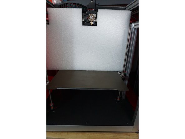
Open the box and remove the top foam
-
-
-
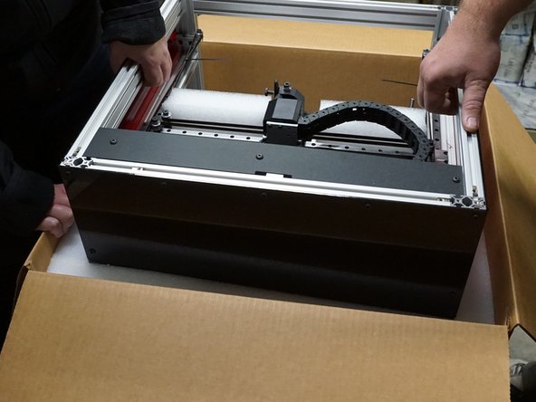
(We recommend having two people for this next step)
-
With one person on opposite sides of the box. Each person should grab the top aluminum with one hand and the top of the box with the other.
-
Pull up evenly on both sides of the unit while pushing down the box.
-
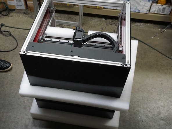
Once the unit is lifted free from the box, center foam, and base foam; place the unit on a table.
-
-
-
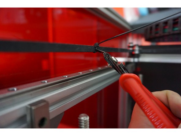
Now you should remove the zip ties from the XY belt system.
-
Gently push your gantry towards the Y max (Rear of the unit)
-
-
-
Slide the bottom white box from under the bed and set it to the side.
-
-
-
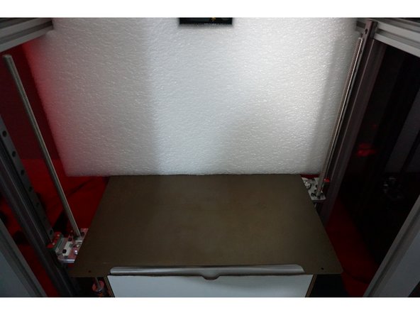
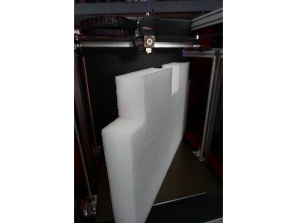
Pull the interior foam out of the unit, it is okay if the front of the bed drops slightly but do not move it all the way down.
-
-
-
Move to the White Box that was removed from below the bed.
-
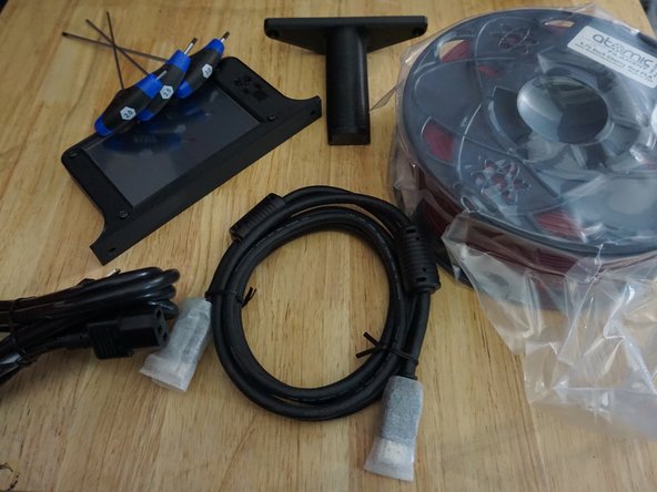
Inside the White Box, you will find the following:
-
1kg spool of filament for first prints.
-
Power Cable and HDMI Cable (for diagnostics)
-
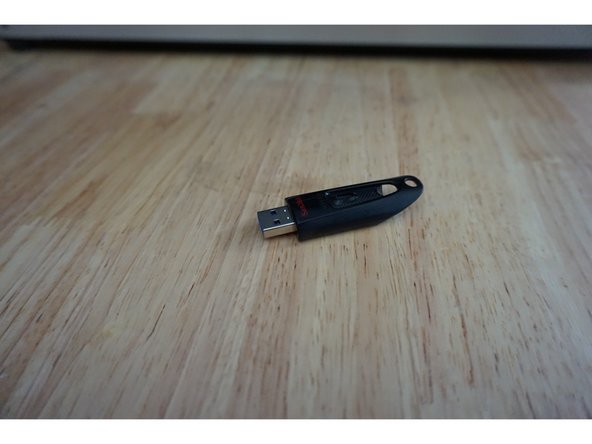
USB stick
-
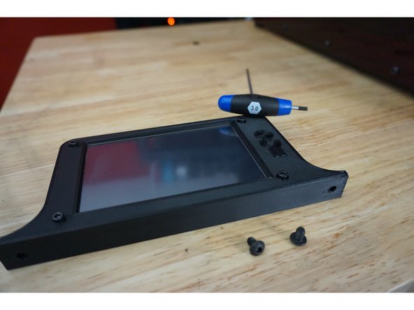
5in Touch Screen and Spool Holder (Two M5x10 bolts to mount the spool holder and two M5x10 bolts to mount the display)
-
Tools: T-Handle Hex 2mm, 2.5mm, 3mm
-
Filament sensor with bowden tube (one M5x10mm bolt for mounting filament sensor)
-
-
-
If you intend to use a wall-mounted spool holder or RepBox, you do not need the spool holder
-
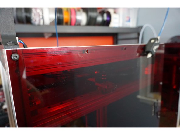
On the right side of the printer, locate the second and third bolts across the top edge from the front that holds the acrylic to the aluminum.
-
Remove the second and third bolt, these bolts will no longer be used.
-
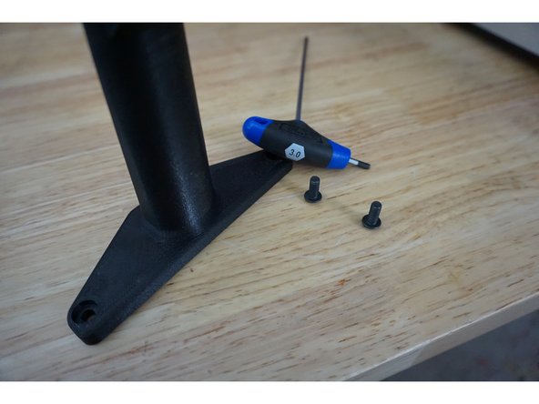
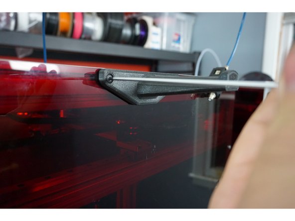
Mount your spool holder using the two M5x10 bolts included.
-
-
-
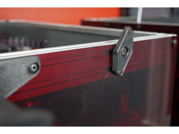
On the right side of the printer, locate the fourth bolt across the top edge from the front that holds the acrylic to the aluminum.
-
Remove the fourth bolt, this bolt will no longer be used.
-
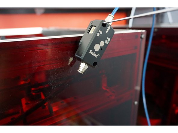
Mount the Filament Sensor mounting plate with the included M5x10mm bolt
-
Mount the Filament Sensor to the mounting plate with the included M3 Bolts ensuring the bowden tube is coming out of the top of the sensor.
-
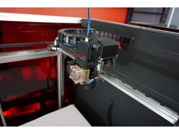
Insert the other side of the bowden tube into the BondTech Extruder.
-
-
-
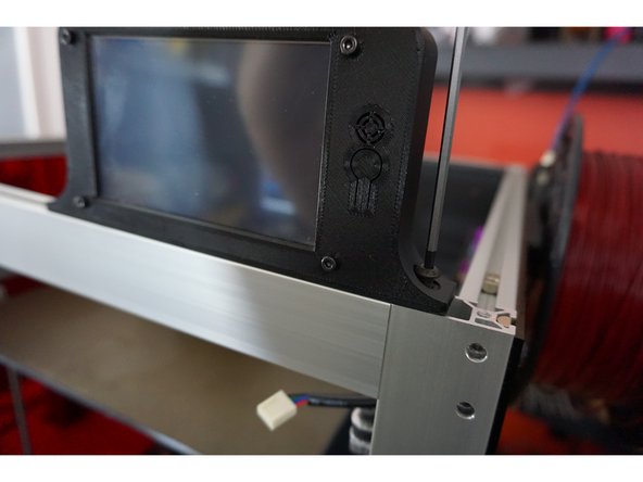
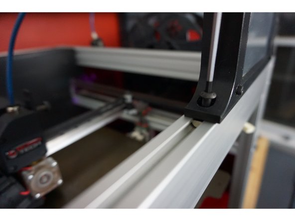
On the top of the unit, your display will mount across the front extrusion.
-
The right M5x10 bolt will go into the tapped end of the aluminum
-
The left M5x10 bolt will go into the slidable nut.
-
-
-
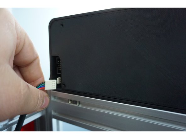
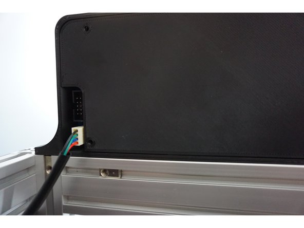
Once the screen is mounted, plug in the screen. The plug is keyed so you can only plug it in one way.
-
-
-
You have two options when it comes to connecting to the internet.
-
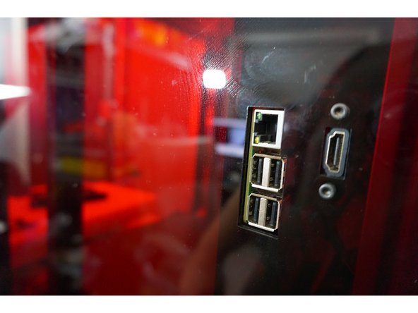
The first option is via the Ethernet port on the right side of the unit, this is recommend for production environments.
-
The next option is via WiFi if Ethernet is not accessible.
-
-
-
What you will need to connect via Ethernet.
-
Daedalus 3D Printer
-
Ethernet Cable (Not Included)
-
Power Cord (Included)
-
-
-
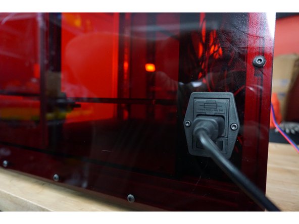
Plugin the power cable to the right side of the unit
-
Ensure the printer is off
-
Plugin the Ethernet to the right side of the printer
-
Plug the USB provided into the machine, wait 3 minutes and remove it. Plug it into a computer and open the IP_ACCESS file which will give you the IP address
-
-
-
What you will need to connect via WiFi.
-
Daedalus 3D Printer
-
Computer
-
Power Cord (Included)
-
USB Drive (Included)
-
-
-
Plugin the included USB Drive into your computer.
-
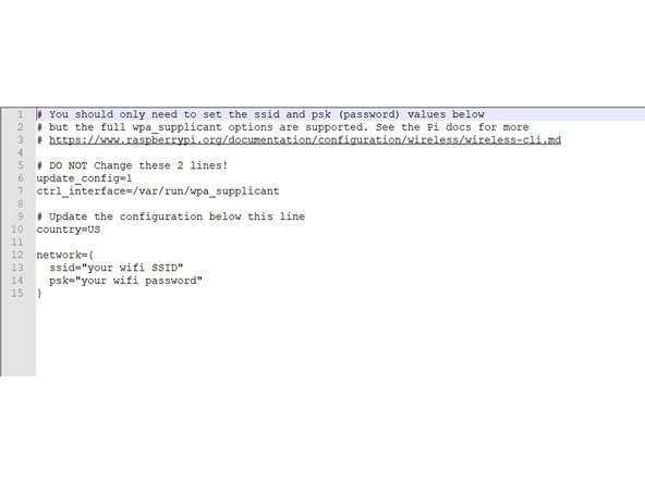
On the USB Drive there is a file called WPA_SUPPLICANT . Open the file and fill in the following information :
-
SSID: (the name of the network you are attempting to connect to)
-
Password: (this is your WiFi password)
-
Save the file and eject your USB Drive.
-
We use Notepad++ for editing your wifi information it can be found here https://notepad-plus-plus.org/
-
-
-
Plug the Power Cord into the right side of the Daedalus Unit.
-
Ensure the unit is off.
-
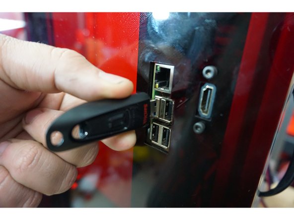
Plug the USB Drive into any of the four open USB ports on the right side of the unit.
-
Power on the unit and wait 3 minutes while the unit powers on. This wait time is only needed when uploading your WiFi information.
-
During this time it will rewrite the onboard WiFi information. Once it's rewritten it will create a file on the USB Drive named (Name) where it will give you the IP address that allows you to access your printer via the web interface.
-
-
-
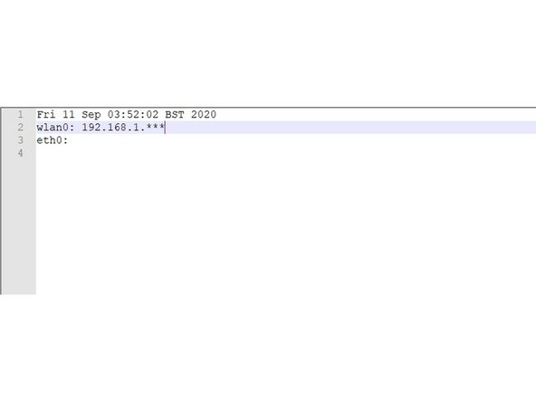
Now you can remove your USB Drive from the unit.
-
Insert the USB Drive back into your computer and open the file named IP_ADDRESS
-
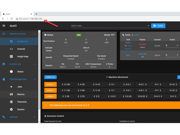
You IP Address will look like this: 192.168.1.***
-
-
-
Open your prefered web browser
-
Enter the IP Address, you were supplied in the previous steps, into the Address Bar and hit enter.
-
Now your web interface load in your browser.
-
If you have any issues connecting to the Web Interface please contact us.
-